Fundamentals
A Stepper Motor is a brush-less, synchronous DC electric motor, which divides the full rotation into a number of equal steps. Its used to rotate pricise distance utilising number of steps.
Stepper Motor can be easily interfaced with PIC Microcontroller but you may use transistor driver circuits because microcontroller can't bear a lot of current.
Wave Drive
In this mode only one stator electromagnet is energised at a time. It has the same number of steps as the full step drive but the torque is significantly less. It is rarely used. It can be used where power consumption is more important than torque.
Wave Drive Stepping Sequence
| ||||
|---|---|---|---|---|
| Step | A | B | C | D |
| 1 | 1 | 0 | 0 | 0 |
| 2 | 0 | 1 | 0 | 0 |
| 3 | 0 | 0 | 1 | 0 |
| 4 | 0 | 0 | 0 | 1 |
Full Drive
In this mode two stator electromagnets are energised at a time. It is the usual method used for driving and the motor will run at its full torque in this mode of driving.
Full Drive Stepping Sequence
| ||||
|---|---|---|---|---|
| Step | A | B | C | D |
| 1 | 1 | 1 | 0 | 0 |
| 2 | 0 | 1 | 1 | 0 |
| 3 | 0 | 0 | 1 | 1 |
| 4 | 1 | 0 | 0 | 1 |
Half Drive
In this stepping mode, alternatively one and two phases are energised. This mode is commonly used to increase the angular resolution of the motor but the torque is less approximately 70% at its half step position (when only a single phase is on). We can see that the angular resolution doubles in Half Drive Mode.
Half Drive Stepping Sequence
| ||||
|---|---|---|---|---|
| Step | A | B | C | D |
| 1 | 1 | 0 | 0 | 0 |
| 2 | 1 | 1 | 0 | 0 |
| 3 | 0 | 1 | 0 | 0 |
| 4 | 0 | 1 | 1 | 0 |
| 5 | 0 | 0 | 1 | 0 |
| 6 | 0 | 0 | 1 | 1 |
| 7 | 0 | 0 | 0 | 1 |
| 8 | 1 | 0 | 0 | 1 |
Driving Bipolar Motor
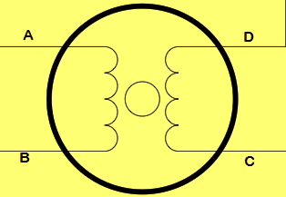
Bipolar motors are simpler in construction as it contains two coil and no centre tap. Being simple, driving is little complex compared to unipolar motors. To reverse the magnetic polarity of stator windings, current through it must be reversed. We can distinguish bipolar motors from unipolar motors by measuring the coil resistance. In bipolar motors we can find two wires with equal resistance.
Bipolar Motor Stepping Sequence
| ||||
|---|---|---|---|---|
| Step | A | B | C | D |
| 1 | 1 | 0 | 0 | 0 |
| 2 | 0 | 0 | 1 | 0 |
| 3 | 0 | 1 | 0 | 0 |
| 4 | 0 | 0 | 0 | 1 |
Application

| Coil A | Coil B | Coil C | Coil D | |
| Step 1 | High | High | Low | Low |
| Step 2 | Low | High | High | Low |
| Step 3 | Low | Low | High | High |
| Step 4 | High | Low | Low | High |
Continues rotation will be occurred when steps 1,2,3,4 repeat.
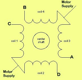
Yellow wire - Coil 1
Brown wire - Coil 2
Red wire - Common power wire
Orange wire - Coil 3
Black wire - Coil 4

Source Code MikroC
void main () {
TRISC=0; //make PORTC output
PORTC=0; // set PORTC value to zero
while(1){ // endless loop
PORTC=3; // PORTC.0 and PORTC.1 make high (coil 1 & 2 energize)
Delay_ms(500); // delay 500ms
PORTC=6; // PORTC.1 and PORTC.3 make high (coil 2 & 3 energize)
Delay_ms(500);
PORTC=12;
Delay_ms(500);
PORTC=9;
Delay_ms(500);}
}
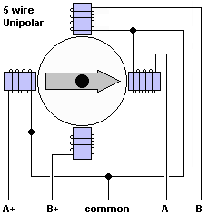
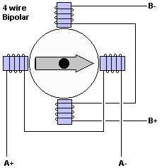
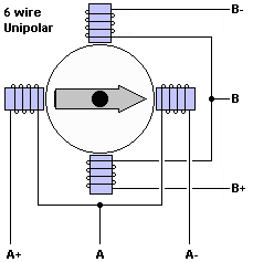
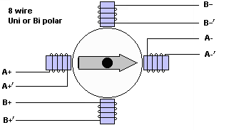
Stepper motor common wiring types,
High Speed Stepper Motor Factors
Several factors become significant designs and implementation challenges when stepper motors are driven at high speeds. Like many components, the real world behaviour of stepper motors is not ideal and a far cry from theory. Stepper motors max speed will vary by manufacturer, model, and the inductance of the motor with speeds of 1000-3000 RPM attainable (for higher speeds, servo motors are a better choice). The main factors that impact stepper motor driving at high speeds are:
Inertia - Any moving object has inertia which resists the change in acceleration of an object. In lower speed applications, it's possible to start driving a stepper motor at the desired speed without missing a step. However, attempting to drive a load on a stepper motor at high speed immediately is a great way to skip steps and lose position. Except for very light weight loads with little inertial effects, a stepper motor must ramp up from low speed to high speed to maintain position and precision. Advanced stepper motor controls include acceleration limitations and strategies to compensate for inertia.
Torque Curves - The torque of a stepper motor is not the same for every operational speed but drops as the stepping speed increases. The reason for this is based on the operational principals of stepper motors. The drive signal for stepper motors generates a magnetic field in the coils of the motor in order to create the force to take a step. The time it takes the magnetic field to come up to full strength depends on the inductance of the coil, drive voltage, and current limitation. As the driving speed increases, the time the coils stay at their full strength shortens and the torque the motor can generate drops off.
Drive Signal - To maximize the force in a stepper motor, the drive signal current must reach the maximum drive current and in high speed applications this must be done as quickly as possible. Driving a stepper motor with a higher voltage signal can help to improve the torque at high speeds which are automatically applied in constant current stepper driver solutions.
Dead Zone - The ideal concept of a motor allows it to be driven at any speed with at worse a reduction of torque as the speed increases. Unfortunately stepper motors often have a dead zone where the motor cannot drive the load at a given speed. This is due to resonance in the system and varies for every product and design.
Resonance - Stepper motors drive mechanical systems and all mechanical systems can suffer from resonance. Resonance occurs when the driving frequency matches the natural frequency of the system and energy added to the system tends to increase its vibration and loss of torque rather than its velocity. In applications where excessive vibrations will have issues, finding and skipping over the resonance stepper motor speeds is especially important. Even applications that can tolerate vibration should avoid resonance where possible since it can significantly lower the life of the system.
Step Size - Stepper motors have a few driving strategies available, including micro stepping which allows smaller than full steps to be made by the motor. These micro steps do not provide increased accuracy (rather micro steps have decreased accuracy) but they do make stepper motor operation quieter at lower speeds. Stepper motors can only be driven so fast, and the motor sees no different in a micro step or a full step. For full speed operation, driving a stepper motor with full steps is often required. However, using micro stepping through the stepper motor acceleration curve can significantly decrease noise and vibration in the system.
A Practical approach,
Imagine you have got a stepper motor but you don't know wiring, how do you find out them, for an application?

No comments:
Post a Comment